The Protolis guide to plastic injection molding
Welcome to our ultimate guide on injection molding. We will uncover the essentials of this manufacturing process, from its rich history to modern applications and design practices, offering straightforward insights into materials, design practices, cost considerations, and more.
Method Type
Jump to page content
Page Content
- The basics of injection molding
- How does the injection molding process work?
- What are the different technologies of injection molding?
- How did injection molding start?
- What are the limitations of injection molding?
- Materials for injection molding
- What are the main materials?
- How to choose the right injection material
- What are the possible finishes for a plastic part?
- Exploring mold-tech textures in injection molding
- What are the applications of injection molding?
- Best design pratices for injection molding
- Define the visible surfaces
- Think about the parting line
- Keep a uniform main body wall thickness – Coring out
- Choose smooth transition when you need thickness variation
- Add ribs wisely to strengthen your parts
- Assembling by using some bosses
- Assembling by using snap-fits
- Undercuts on the outside surface
- Find the interference and keep the right gaps
- Add draft angle to your parts
- Add some radius on corners
- Last step: fix your tolerance
- Cost optimisations for injection molding?
- Conclusion
The basics of injection molding
In the injection molding (IM) process, polymers are heated to a fluid state before being, injected into a mold under high pressure. Inside, it takes the shape of the cavity after cooling. The result is a precise, solidified part ready for use.
Key to injection molding’s appeal is the ability to produce vast quantities of parts with uniform quality. Each cycle, often under 30 to 60 seconds, yields multiple components. This efficiency makes it a go-to method for mass production.
The process excels in creating complex shapes, rivaling metal casting, and 3D printing. Despite the high initial investment in molds, the per-unit cost remains low. This balance of cost and versatility makes injection molding a popular choice across industries, although the initial setup time and cost can be significant.
How does the injection molding process work?
The injection molding machine
The core job of an injection molding machine is melting plastic granules, injecting them into a mold, and then releasing the cooled, formed parts. The IM machine consists of three main components: the injection unit, the clamping unit, and the mold itself.
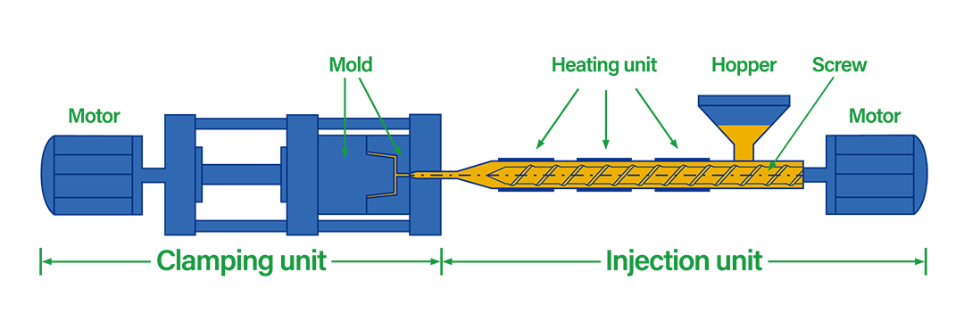
Figure 1: Injection molding machine overview
- Injection unit: This section consists of the material feeding hopper, a heated barrel, and an screw, all driven by a hydraulic ram. The screw not only mixes but also heats the material, pushing the molten plastic into the mold. Its design is crucial, optimizing pressure and melting efficiency.
- Clamping unit: Here, the two mold halves are securely held together against the injection force. This unit ensures the mold opens and closes in sync with the injection cycle, maintaining perfect alignment.
- The mold: A split metal block, the mold features cavities shaped as the desired parts. The molds are commonly made from steel and can feature single or multiple cavities. This versatility allows molding one or several parts in a single cycle. The design of the mold is essential, as it influences the quality and efficiency of the final product.
Each component plays a vital role in ensuring the injection molding process is efficient, precise, and capable of handling diverse production needs.
The injection molding process: Step-by-step
The injection molding process begins with mold manufacturing. After designing and constructing the mold, manufacturers run trials to fine-tune process parameters. The initial samples, known as T1, undergo customer evaluation.
- Feeding the material: The process starts by filling the feed hopper with dried polymer granules, color pigments, and additives. These materials then move into the barrel.
- Material preparation: Inside the barrel, a reciprocating screw heats, mixes, and pushes the material toward the mold. This step is crucial to prepare the material for injection.
- Molding cycle initiation: The injection molding cycle begins when the material reaches the optimal temperature. The machine closes and clamps the mold halves together, readying them for injection.
- Injection of the material: The screw driven by the hydraulic cylinder pushes the molten plastic into the mold cavity. This process, called a shot, fills the cavity through mold runners.
- Cooling and solidification: Upon contact with the mold’s cooler surface, the plastic cools and solidifies. The ram applies continuous pressure to compensate for material contraction during cooling.
- Ejection of the molded part: Once solidified, the injection unit retracts, and the clamping unit opens the mold. Ejectors pins of the mold then release the molded part.
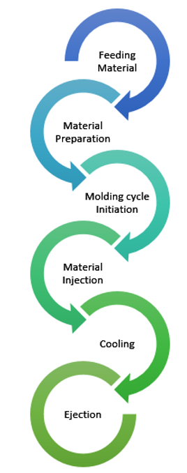
Figure SEQ Figure \* ARABIC 2: Step-by-step guide to the injection molding process
Post-processing includes removing excess material and surface finishing like painting or electroplating.
What are the different technologies of injection molding?
In addition to conventional plastic injection molding, there are several other technologies that address specific needs and various applications. These processes offer optimized solutions for complex geometries, multiple material requirements, or the production of lightweight or highly precise parts. Here is an overview of the different plastic injection molding techniques that expand manufacturing possibilities:
Insert molding is a process where pre-formed components, such as metal inserts, are placed into a mold, and plastic is injected around them to create a single, integrated part. This technique is commonly used to combine plastic with other materials, providing added strength, conductivity, or threaded features, without the need for additional assembly. It is often used in applications like electrical components, fasteners, and medical devices.
This technique combines traditional injection molding with pressurized inert gas, usually nitrogen. The process begins by filling the mold with molten plastic, covering about 70% to 80% of the cavity. Then, nitrogen gas is injected to push the plastic against the mold’s walls, creating large, hollow parts. The result? Enhanced surface finishes and precise geometries.
Also known as liquid injection molding or LSR molding, this process produces flexible, durable silicone parts. It starts by mixing two components: silicone and a platinum catalyst. After thorough mixing at low temperatures, the mixture is injected into a heated mold for curing. This method is crucial in industries needing flexible, heat-resistant parts, like automotive and healthcare.
A two-shot molding process, 2K color injection molding allows for complex designs and enhanced functionality. It simultaneously injects two different materials into the mold. Typically, a rigid material like polypropylene is combined with an elastomeric one like TPE. The significant advantage of this technique is that it removes extra steps like painting after molding, making production smoother and maintaining a high-quality finish.
How did injection molding start?
Injection molding, a pivotal process in the plastics industry, has a rich history that dates back to 1872. This journey, marked by significant milestones, transformed manufacturing.
Tracing the evolution
- The Genesis (1872): Isaiah and John Hyatt invented the first molding machine, primarily for buttons and combs. This invention laid the foundation for the plastics industry.
- Early Improvements (1903): German scientists Arthur Eichengrün and Theodore Becke enhanced the process. They developed soluble forms of cellulose acetate, reducing flammability and improving usability.
- The 1930s: This era saw remarkable advancements. Key thermoplastic materials like polyvinyl chloride, polystyrene, and polyolefins emerged, expanding the scope of plastic products.
- A Significant Leap (1919 and 1939): Arthur Eichengrün played a crucial role in advancing injection molding. In 1919, he developed the first injection molding press. By 1939, he patented the injection molding of plasticized cellulose acetate, setting new industry standards.
- The Game Changer (1946): James Watson Hendry revolutionized the process with the extrusion screw injection machine. This innovation allowed for greater control and higher quality in plastic products.
Each stage reflects the evolving nature of injection molding, showcasing its journey from a simple mechanism to a sophisticated manufacturing process.
What are the benefits of injection molding?
Injection molding offers several benefits, making it a preferred choice for manufacturing plastic parts for various industries.
Injection molding stands out for its swift production once the molds are established. With cycle times of a few seconds, it efficiently handles medium to high-volume production. Quantities can range from a few thousand to millions of parts, depending on the molds. Utilizing multi-cavity or family molds further amplifies production rates by creating multiple parts per press.
This process allows for the precise reproduction of complex details, making it ideal for parts with intricate and fine shapes. Through the use of advanced mold designs and carefully controlled production parameters, manufacturers can produce parts that meet strict dimensional tolerances in the range of hundredths of a millimeter.
| Production Volume Category | Low-Volume | Mid-Volume | High-Volume |
|---|---|---|---|
| Production Volume | 100 units | 5,000 units | 100,000 units |
| Mold Type | 3D printed polymer | Machined aluminum | Machined steel |
| Lead Time | 2-3 days | 2-3 weeks | 5-7 weeks |
| Mold Cost | $100 | $3,000 | $20,000 |
| Material Cost | $0.50 per part | $0.50 per part | $0.50 per part |
| Labor Costs or Outsourcing Cost | $2.50 per part | $1.50 per part | $1.00 per part |
| Total Production Cost | $400 | $13,000 | $170,000 |
| Cost per Part | $4 | $2.60 | $1.70 |
For high-volume production runs, the cost per plastic part is notably low. In scenarios where the volume ranges from 500 to 5,000 parts, utilizing aluminum molds instead of steel can sometime keep costs down, offering a cost-effective solution for medium production.
One of the primary advantages of plastic injection molding is its consistency. A single mold can yield thousands of parts before requiring maintenance. An aluminum mold typically lasts 5,000 to 10,000 cycles, while a steel production mold can exceed 1,000,000 cycles. The uniformity of the process ensures that each part produced is identical, maintaining quality across all products.
Injection molding is distinct for its efficient use of materials. While some scrap is inevitable, the process minimizes waste effectively. Excess materials like sprues and runners can be ground up, melted, and reused, making the most of every bit of plastic. This recycling aspect conserves materials and plays a part in environmental sustainability.
Injection molding process is compatible with a vast array of over 25,000 engineered materials. This wide variety provides options to meet specific product requirements. Materials like ABS, PE, PS, and PP are widely used. The process also allows for the creation of composites by mixing materials, such as adding glass fibers to thermoplastics for increased strength. Color customization is also versatile, with options like masterbatches and liquid colorants, offering extensive product design flexibility.

In terms of production speed, injection molding excels. Most molding cycles complete within 10 to 60 seconds, contrasting to the time taken by other processes like 3D printing or CNC machining. For complex geometries, even if the cycle takes around 120 seconds, the ability to mold several smaller parts simultaneously enhances efficiency. This feature rapidly produces hundreds of identical parts per hour, optimizing time and cost efficiency.
These features make injection molding an attractive option for manufacturers who need efficient, precise, and cost-effective production of plastic parts.
What are the limitations of injection molding?
Injection molding, while advantageous for mass production, has notable constraints that require careful consideration in the planning phase.
Investing in high-volume production using steel molds entails significant upfront costs and extensive machining work. This process can span up to 12 weeks, representing a considerable initial investment. The per-part cost increases for smaller quantities, suggesting alternative methods such as aluminum molds might be more economical.
Consider production methods like CNC machining or 3D printing for low production requirements. By doing this, you can avoid the high lead time and cost required to manufacture the mold.
Flexibility in terms of modification is very limited with injection molding compared to other processes. Modifying a part by adding new shapes or functions may require the production of a new mold, leading to additional costs and delays. To minimize these costs, it is crucial to begin injection tooling only once the part design has been validated. For this reason, we recommend going through a prototyping phase using 3D printing or CNC machining.
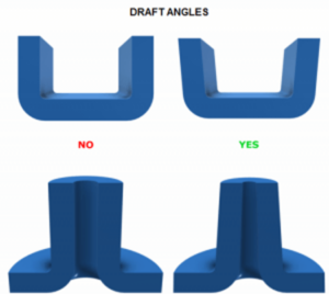
Design intricacies often impose restrictions on injection molding. To facilitate part ejection, incorporating draft angles and rounded edges is essential. It’s crucial to avoid undercuts and maintain consistent wall thickness for integrity and manufacturability. Placing gates and ejectors requires strategic planning when the part’s appearance is a priority. Modifying a mold design after production starts is not straightforward. While adding material to a part is feasible, reducing material is not; retooling might be necessary. These design considerations are pivotal for a seamless transition from concept to final product.
Injection molding offers substantial benefits for large-scale production but requires careful consideration of initial expenditures and design flexibility. Early collaboration with our experts can streamline the process, ensuring designs are optimized for production and cost-efficiency.
Materials for injection molding
The spectrum of materials available for injection molding is impressively vast, each with distinct characteristics to match specific product requirements. Commonly selected materials include durable ABS, versatile PS, tensile strenght PP, and flexible PE. PMMA stands out for its clarity and light transmittance. Each option presents unique advantages: impact resistance, flexibility, or thermal stability. Manufacturers can select materials based on the final product’s desired durability, texture, and resilience.
What are the main materials?
Injection molding utilizes a range of materials, each imparting unique properties to the final product. Explore 10 commonly used materials shaping diverse applications.
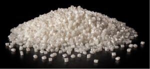
ABS combines ease of molding with the ability to be colored and finished in various textures. It’s challenging and performs well under impact but isn’t suited for prolonged outdoor use due to limited UV, water, and weather resistance.
Applications:
Some common uses of ABS material in injection molding include:
- Computer keyboard keys
- Casing for electronic products
- Automotive components
- Various consumer and industrial products.
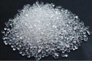
Noted for its strength and transparency, PC is preferred for items needing optical clarity. It withstands a broad temperature range and provides excellent dimensional control during molding. However, its need for high processing temperatures can add to production costs.
Applications:
PC is generally used to produce the following items:
- Protective machinery guards
- Transparent windows
- Safety helmets
- LED diffusers and light pipes
Due to the BPA content in PC, it’s not recommended for producing food-related products.
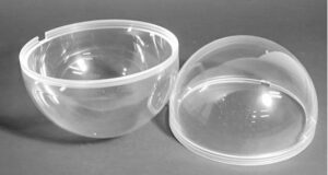
Acrylic shines with its glass-like clarity and resistance to shattering, UV light, and weathering. It’s a durable choice for applications where light transmission is crucial. Despite its tensile strength, acrylic can be susceptible to stress cracking and is sensitive to solvents and oils.
Applications:
PMMA is employed in products like:
- Windows and greenhouses
- Solar panel components
- Bathroom enclosures
- Transparent elements in architecture and lighting
Grades:
- General-purpose acrylic is widely used for various common products.
- Sign-grade acrylic, offering enhanced strength and light transmission, is ideal for outdoor signs.
- Marine-grade acrylic stands up to ongoing water exposure and is suitable for marine environments.
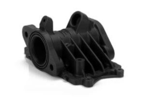
Nylon blends durability with high heat resistance, offering excellent abrasion and fatigue resistance. While not naturally flame-resistant, additives can enhance its performance against fire and UV exposure. Nylon’s resilience to wear and its ability to dampen noise make it popular, though it is more susceptible to strong acids and oxidizing agents than other plastics. Injection molding nylon can be complex due to its shrinking tendency and incomplete mold filling.
Applications:
- Bearings, bushings, gears, and slides that require strength
- Enclosures for casings and snap-fit components
- Robust threaded inserts and moving parts
- Jigs and fixtures for manufacturing settings
Grades:
- Nylon 11 for outdoor applications with stability against dimensional changes.
- Nylon 12 for the lowest water absorption and melting point.
- Nylon 46 for the highest temperature operations.
- Nylon 66 for superior acid resistance and high melting point.
- Glass fiber-filled nylon for enhanced strength.
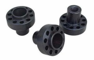
PE is moisture and chemical-resistant. It is a versatile material with variants like HDPE and LDPE, each offering different hardness levels and flexibility. HDPE is more rigid but less flexible than LDPE, which can be as transparent as glass. PET, a non-density-specific type of PE, offers varying clarity levels.
Applications:
- Indoor uses due to poor UV resistance.
- Products requiring chemical resistance but not high-temperature endurance.
- Commonly found in housewares, toys, food containers, and automotive parts.
Grades:
- Numbered grades indicate density levels; higher numbers generally mean higher density.
- HDPE varieties are denser and sturdier than the softer, more flexible LDPE.
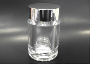
Polystyrene balances cost-efficiency and performance with options like GPPS and HIPS, catering to different application needs. GPPS offers clarity but is brittle, while HIPS is tougher with less clarity. Both types resist moisture and bacterial growth and are suitable for sterilized medical devices.
Applications:
- Medical, optical, and electrical sectors value PS for specific device requirements.
- HIPS is utilized in appliances for its higher impact strength.
- GPPS finds its place in manufacturing toys, cases, and various containers.
Grades:
- Glass-filled polystyrene increases strength.
- Copolymers with acrylic enhance clarity and stability against chemicals and UV light.
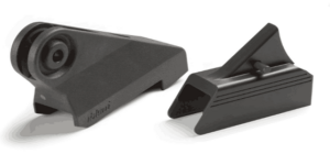
POM, widely recognized as acetal, offers a blend of rigidity, thermal stability, and a low friction coefficient. This engineering plastic has minimal water absorption and stands up well against chemicals. Pure acetal is known for its low-impact strength and thermal expansion. However, reinforcing POM with fiberglass or minerals enhances its strength and rigidity. Its susceptibility to UV limits its outdoor applications.
Applications:
- Bearings and gears benefit from their friction properties.
- Conveyor belts and pulley wheels operate smoothly with POM parts.
- It’s also used in eyeglass frames and parts for knives and firearms.
Grades:
- Homopolymers provide higher hardness and tensile strength.
- Copolymers of POM are available with varied properties.
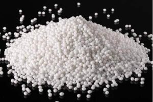
PP is a widely used material known for its durability, chemical resistance, and shape retention, even after bending or torsion. It’s recognized for its high melting point and immunity to moisture. While PP boasts numerous advantages, it has its drawbacks, such as UV degradation and high flammability. It also releases aromatic hydrocarbons at elevated temperatures and can be challenging to bond or paint.
Applications:
- Commonly used for toys and storage containers.
- Sporting goods and various packaging solutions.
- Household appliances and power tool bodies.
Grades:
- Standard polypropylene is lightweight yet strong.
- Glass-fiber-filled high crystalline polypropylene (HcPP) offers increased rigidity.
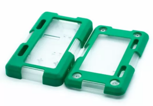
TPE, a fusion of plastic and rubber, combines the processability of plastics with the functional characteristics of elastomers. It exhibits elasticity and returns to its original shape when stretched. TPE molds are easier and cost less than liquid silicone rubber but tend to deform permanently under constant pressure. High temperatures may also reduce its elasticity. Despite these factors, its recyclability makes it a sustainable option.
Applications:
- Widely used in the creation of comfortable footwear.
- Essential in producing flexible medical devices.
- Integral to various auto parts for flexibility and durability.
- Famous in pet products for chew resistance and softness.
Grades:
Commercial TPEs are categorized by ISO 18064 standards, ensuring consistent application quality.
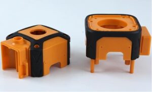
TPU stands out in the TPE family for its remarkable properties. It mimics rubber’s elasticity and offers enhanced load-bearing capacity. TPU outperforms TPE in extreme temperature and chemical resistance. It is known for its toughness but may require pre-processing drying to ensure optimal molding conditions.
Applications:
- Utilized in footwear for its flexibility and strength.
- Forms effective gaskets and caster wheels due to its durability.
- Used in sporting goods for its resilience.
- Protective for electronics and medical devices as enclosures and casings.
Grades:
TPUs are available in various grades tailored for commercial, medical, and industrial use, encompassing polyester, polyether, and polycaprolactone types, each offering distinct properties for specialized applications.
These 10 materials highlight injection molding’s adaptability in creating products for various industries. Understanding their properties ensures suitable material selection for your project.
How to choose the right injection material
Selecting the appropriate injection molding material is important for achieving the desired quality and functionality of the final product. Here are key factors to consider:
- Strength: Determine the required strength of the material based on the application’s load-bearing needs. Higher-strength materials withstand greater forces without deforming or breaking.
- Stiffness: This attribute defines how much a material resists deformation under stress. Stiffer materials maintain their shape better but may be more prone to breaking under impact.
- Impact resistance: Choosing a material with high impact resistance is crucial if the product is likely to experience sudden forces or drops. This ensures durability and longevity in challenging conditions.
- Compatibility: The material should be compatible with other components of the product, especially if it is part of a larger assembly. It should not react negatively when in contact with other materials or substances.
- Chemical resistance: Products exposed to harsh chemicals or environments need materials that resist corrosion or degradation. This is vital for preserving the product’s appearance and functionality over time.
- UV concerns: UV resistance is essential for products used outdoors or exposed to sunlight. Materials without UV stability can degrade, losing color and structural integrity.
- Temperature: Consider the operating temperature range of the product. Materials should withstand the maximum and minimum temperatures without losing their properties.
- Flammability: Opt for materials with low flammability ratings in applications where fire safety is a concern. This is particularly important in automotive, electrical, and building applications.
Understanding the demands of your specific application and the environment in which the product will be used guides the choice of the right injection molding material.
| Material Name | Brands | Strength | Impact Resistance | Temperature Stability | Relative Cost |
| PMMA | Plexiglas, Acrylite | Medium | Low | Low | Medium |
| TPE | Santoprene | Low | High | Low | Low – Medium |
| PS | Styron | Low – Medium | Low | Low | Low |
| PBT | Valox, Crastin | Medium | High | Low | Medium – High |
| PBT et PET chargé de verre | Valox, Crastin, Rynite | High | Medium | Medium | Medium – High |
| ABS | Lustran, Cycolac | Low – Medium | High | Low | Low |
| PEHD | Dow HDPE, ChevronHDPE | Low | High | Low | Low |
| PP | Maxxam, Profax | Low | High | Low | Low |
| Nylon, PA 6/6 | Zytel | Medium | High | Low | Medium |
| Nylon, PA 6/6 chargé de verre | Zytel | High | Medium | High | Medium |
| POM (Acétal) | Delrin, Celcon | Medium | Medium | Low – Medium | Medium |
| PC (Polycarbonate) | Lexan, Makrolon | Medium | High | Medium – High | Medium – High |
| ABS/PC | Cycoloy, Bayblend | Medium | High | Medium | Medium |
What are the possible finishes for a plastic part?
The desired surface finish must be considered from the design phase of the part, by incorporating several additional factors such as material selection, molding conditions, and mold finish. These elements influence both the final appearance and feel of the part. For finishes coming directly from the mold, it is essential to understand that selecting an appropriate surface texture can significantly impact both the aesthetics and the functional performance of the part. This is why it is crucial to address this issue early in the design for manufacturing (DFM) process.
We offer guidance on this intricate decision, ensuring the chosen finish aligns with your vision for the final product. This collaborative process helps achieve the desired outcome with precision and clarity.
Why use different surface finishes?
Enhancing aesthetics
Surface finishes play a crucial role in enhancing the final appearance of products. Designers often prefer matte textures to elevate the product’s aesthetics while concealing imperfections such as tool marks, sink marks, or weld lines. A well-executed finish not only hides these flaws but also gives the product a high-end, refined look, thereby increasing its visual appeal in the market.
Functional advantages
Beyond aesthetics, the choice of surface finish serves practical purposes. For products requiring a secure grip, textured finishes are invaluable. They improve the grip quality, which is essential for slip-resistant items.
1. SPI injection molding surface finish standards
The SPI (Society of the Plastics Industry) surface finish standards provide a comprehensive framework for categorizing the surface roughness of plastic parts. Defined by the Plastics Industry Association, these standards range from glossy to textured finishes, organized into four distinct grades: A, B, C, and D.
| Finish | SPI* standard | Finishing method | Surface roughness Ra (μm) |
| Super High Gloss | A-1 | Grade #3, 6000 Grit Diamond Buff | 0.012 – 0.025 |
| High Gloss | A-2 | Grade #6, 3000 Grit Diamond Buff | 0.025 – 0.05 |
| Medium Gloss | A-3 | Grade #15, 1200 Grit Diamond Buff | 0.05 – 0.10 |
| Fine Semi-gloss | B-1 | 600 Grit Paper | 0.05 – 0.10 |
| Medium Semi-gloss | B-2 | 400 Grit Paper | 0.10 – 0.15 |
| Normal Semi-gloss | B-3 | 320 Grit Paper | 0.28 – 0.32 |
| Fine Matte | C-1 | 600 Grit Stone | 0.35 – 0.40 |
| Medium Matte | C-2 | 400 Grit Stone | 0.45 – 0.55 |
| Normal Matte | C-3 | 320 Grit Stone | 0.63 – 0.70 |
| Satin Textured | D-1 | Dry Blast Glass Bead #11 | 0.80 – 1.00 |
| Dull Textured | D-2 | Dry Blast #240 Oxide | 1.00 – 2.80 |
| Rough Textured | D-3 | Dry Blast #24 Oxide | 3.20 – 18.0 |
| As machined | – | – | 3.20 (with visible machining marks) |
Grade A: The pinnacle of gloss

Figure 15: SPI grade A-1, A-2, and A-3 surface finish
Grade A, the highest standard in the industry, achieves a glossy finish through diamond buffing. This category includes levels A-1, A-2, and A-3, each representing varying degrees of polish intensity. A-1 is the glossiest, achieved with fine diamond paste and a rotary tool, descending through A-2 and A-3 with slightly less polish.
| SPI finish | Excellent | Good | Average | Not recommended |
| A-1 (Super high gloss finish) | Acrylic | ABS, PC, PS, Nylon | HDPE, PP, TPU | |
| A-2 (High gloss finish) | Acrylic | PC | ABS, HDPE, PP, PS, Nylon | TPU |
| A-3 (Medium gloss finish) | Acrylic, PC | ABS, PS, Nylon | HDPE, PP | TPU |
Grade B: Mediuam gloss finish
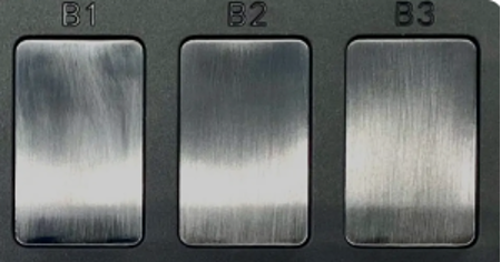
Figure 16: SPI grade B-1, B-2, and B-3 surface finish
For a semi-gloss finish, Grade B employs grit sandpaper. This category also includes three levels: B-1, B-2, and B-3, determined by the grit size of the sandpaper used. B-1 offers a higher gloss level, gradually decreasing through B-2 and B-3, with B-3 being the least glossy in this group.
| SPI finish | Excellent | Good | Average | Not recommended |
| B-1 (Semi-gloss) | PS | ABS, Acrylic, HDPE, PC, PP, Nylon | ||
| B-2 (Medium gloss) | PS, Nylon | ABS, Acrylic, HDPE, PC, PP, Nylon | TPU | |
| B-3 (Low, medium gloss) | ABS, HDPE, PP, PS, Nylon | Acrylic | PC, TPU |
Grade C: Matt finish
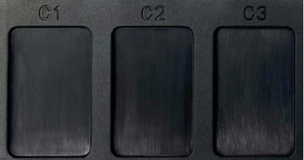
Figure 17: SPI grade C-1, C-2, and C-3 surface finish
Grade C is the choice for a matte finish, using grit sanding stones. Like Grades A and B, it comprises three levels: C-1, C-2, and C-3, with the grit size of the stones dictating the level of matte finish. A higher grit results in a more polished mold, thus a less matte finish.
| SPI finish | Excellent | Good | Average | Not recommended |
| C-1 (Matte) | ABS, HDPE, PS, PP, Nylon | Acrylic, TPU | PC | |
| C-2 (Matte) | ABS, HDPE, PS, PS, Nylon | Acrylic, TPU | PC | |
| C-3 (Matte) | ABS, HDPE, PS, PS, Nylon | Acrylic, TPU | PC |
Grade D: Textured finish
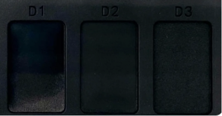
Figure 18: SPI grade D-1, D-2, and D-3 surface finish
Grade D employs pressure blasting with glass beads or aluminum oxide grains to achieve a textured finish. Its internal levels, D-1, D-2, and D-3, reflect the intensity of the texturing process. This grade is particularly suitable for parts requiring a tactile surface.
| SPI finish | Excellent | Good | Average | Not recommended |
| D-1 (Satin) | ABS, HDPE, PC, PP, PS, Nylon, TPU | Acrylic | ||
| D-2 (Dull) | ABS, HDPE, PS, PS, Nylon, TPU | Acrylic | PC | |
| D-3 (Rough) | HDPE, PP | ABS, PS, Nylon, TPU | Acrylic | PC |
The SPI surface finish standards offer a structured approach to achieving the desired surface quality in plastic parts. Each grade, from glossy to textured, serves a specific aesthetic and functional purpose in product design.
2. VDI injection molding surface finish
VDI surface finish, established by Verein Deutscher Ingenieure, is a mold texture standard commonly achieved through electrical discharge machining (EDM). A frequent query in the industry is the distinction between VDI and SPI surface finishes. Essentially, the smoothest grade attainable with VDI is comparable to a Grade C in the SPI standard. This comparison indicates that SPI finishes can achieve smoother textures than those possible with VDI.
| VDIValue | Description | Applications | Surface roughness(Ra) | Mean roughness depth(Rz) | Draft angle – °per side | ||
| µm | µm | ABS | PC | PA | |||
| 12 | 600 Stone | Low polish parts | 0.4 | 1.5 | 0.5° | 1° | 0° |
| 15 | 400 Stone | Low polish parts | 0.56 | 2.4 | 0.5° | 1° | 0.5° |
| 18 | Dry Blast Glass Bead | Satin finish | 0.8 | 3.3 | 0.5° | 1° | 0.5° |
| 21 | Dry Blast #240 Oxide | Dull finish | 1.12 | 4.7 | 0.5° | 1° | 0.5° |
| 24 | Dry Blast #240 Oxide | Dull finish | 1.6 | 6.5 | 1° | 1.5° | 0.5° |
| 27 | Dry Blast #240 Oxide | Dull finish | 2.24 | 10.5 | 1.5° | 2° | 1° |
| 30 | Dry Blast #24 Oxide | Dull finish | 3.15 | 12.5 | 2° | 2° | 1.5° |
| 33 | Dry Blast #24 Oxide | Dull finish | 4.5 | 17.5 | 2.5° | 3° | 2° |
| 36 | Dry Blast #24 Oxide | Dull finish | 6.3 | 24 | 3° | 4° | 2.5° |
| 39 | Dry Blast #24 Oxide | Dull finish | 9 | 34 | 4° | 5° | 3° |
| 42 | Dry Blast #24 Oxide | Dull finish | 12.5 | 48 | 5° | 6° | 4° |
| 45 | Dry Blast #24 Oxide | Dull finish | 18 | 69 | 6° | 7° | 5° |
Understanding the differences between these two standards (SPI and VDI) is crucial for manufacturers to make informed decisions when selecting the appropriate surface finish.
3. Chemical etching
Chemical etching is a precise method for creating textures on mold surfaces. This process involves covering the mold with a special film and then immersing it in an acid bath. The acid selectively etches the unprotected areas, crafting the intended texture. Due to its complexity, chemical etching is often outsourced to specialized facilities, which takes about 2 to 10 days.
This finish must be considered during the part design phase (DFM), as the minimum draft angle for textured surfaces will depend on the type of texture. The application of the texturing is done as the final step, once the part’s geometry has been confirmed.
Exploring mold-tech textures in injection molding
Mold-Tech textures are categorized into several series, such as A and B, each marked by unique MT codes. Created through chemical etching or laser, these textures vary in depth and pattern, offering a range of finishes from fine to coarse matte.
| Mold-Tech Series A | ||
| Pattern # | Depth(mm) | Depth(min) |
| MT-11000 | 0.01016 | 1˚ |
| MT-11010 | 0.0254 | 1.5˚ |
| MT-11020 | 0.0381 | 2.5˚ |
| MT-11030 | 0.0508 | 3˚ |
| MT-11040 | 0.0762 | 4.5˚ |
| MT-11050 | 0.1143 | 6.5˚ |
| Mold-Tech Series B | ||
| Pattern # | Depth(mm) | Depth(min) |
| MT-11200 | 0.0762 | 4.5˚ |
| MT-11205 | 0.0635 | 4˚ |
| MT-11210 | 0.0889 | 5.5˚ |
| MT-11215 | 0.1143 | 6.5˚ |
| MT-11220 | 0.127 | 7.5˚ |
| MT-11225 | 0.1143 | 6.5˚ |
Series A is particularly popular for its diverse range, including finishes that don’t necessitate laser or specialized etching methods. For instance, MT-11010 resembles sand, MT-11120 mimics smooth concrete, and MT-11555 gives a wood panel effect. This series encompasses various textures like a checkerboard, diamond, and line patterns, catering to different aesthetic needs.
- Mold texturing: Draft angle considerations
When applying Mold-Tech textures, considering the draft angle is crucial. Coarser textures require a more aggressive draft angle—typically, an additional 1.5° for every 0.001 in texture depth is recommended. This ensures easier ejection of the part from the mold and maintains the integrity of the texture.
- Other texturing options
In addition to Mold-Tech, the injection molding industry benefits from global alternatives like YS Texture or some other texturing companies offering texturing capabilities and services.
YS Texture, a renowned name in Asia, provides a diverse range of mold textures. Known for its precision and quality, YS Texture caters to various industrial requirements, offering textures that range from very fine to more pronounced patterns. YS Texture has established itself as a reliable alternative. Its presence enhances the choices available to designers and manufacturers.
What are the applications of injection molding?
Injection molding has a wide range of applications across various industries due to its versatility in producing high-quality, precise, and durable parts.
Automotive parts
The automotive industry heavily relies on the injection molding process for both interior and exterior parts. Key components include grills, bumpers, headlights, fenders, side mirrors, splash guards, dashboard elements, door handles, and center consoles.
Common materials used in this sector are polypropylene (PP) for non-critical parts, PVC for weather resistance, and ABS for high-impact strength.
Electronics parts
In the electronics industry, injection molding is crucial for creating corrosion-resistant housings that protect electronic components from harsh environments and temperature changes. Parts such as battery enclosures, conduits, components for laptops and desktop computers, cases and enclosures for circuit boards, and electrical switches are commonly produced.
ABS and polystyrene (PS) are preferred materials due to their impact resistance and electrical insulation properties.
Aerospace parts
Aerospace components require lightweight, durable materials and can withstand extreme temperature fluctuations. Commonly molded parts include bezels, chassis components, enclosures, housings, and panels.
Medical products
The medical industry uses plastic injection molding for manufacturing various components, adhering to strict FDA and ISO certifications. Products include plastic enclosures for medical instruments, transparent parts, and MRI machine components. Popular materials are medical-grade silicone for sterilizable and biocompatible components and ABS, PP, and PE for less critical applications.
Agriculture
In agriculture, injection molded parts offer high impact, humidity, and temperature resistance. Commonly manufactured items include crates, pallets, animal troughs, irrigation system components, and packaging materials.
Toys
Injection molding is integral in the toy industry, exemplified by the manufacturing of Lego blocks. This method ensures uniformity and durability, which is essential for toys that need to fit together accurately.
Consumer products
In the consumer sector, plastic injection molding is used to make a vast array of household items like containers, tubs, drinkware, kitchenware, and outdoor furniture. The durability and adaptability of the plastics used make them ideal for everyday use.
Each of these sectors leverages injection molding for its ability to produce high-quality, durable, and precise components, making it an indispensable process in modern manufacturing.
Best design pratices for injection molding
Plastic injection molding is an advanced technology that requires adherence to specific guidelines to achieve optimal results. In this section, we provide an essential guide to designing plastic parts effectively, ensuring success in production.
Define the visible surfaces
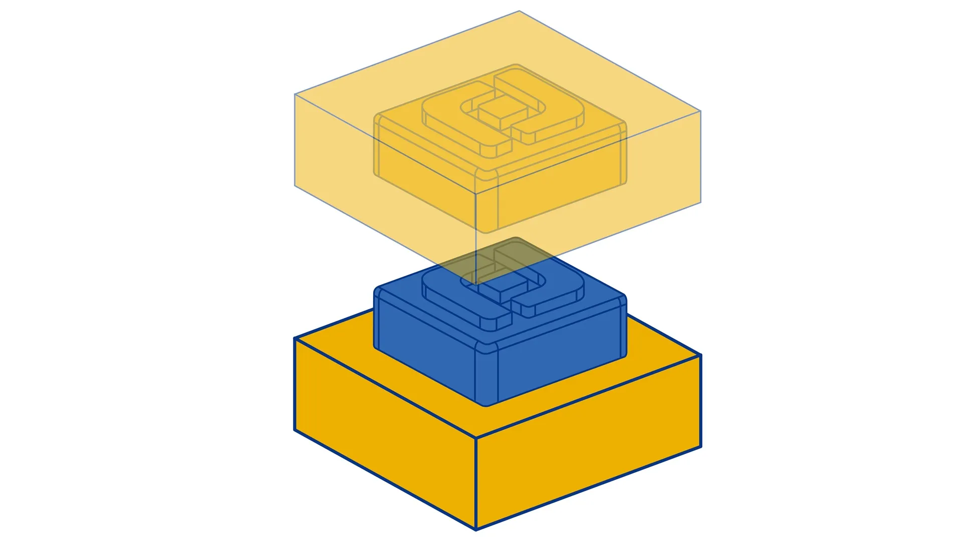
When beginning your project, it’s essential to identify which surfaces need to remain mark-free. These surfaces should be positioned on the cavity side of the mold, as the opposite side, the core side, is where the ejection mechanism is located and where ejector marks may be visible.
Additionally, the placement and type of the gate, which is the entry point for the molten material into the mold, is a crucial consideration. There are various gating options, each with numerous parameters that can significantly impact the quality and appearance of the final product. Given the complexity, few lines will not be enough to explain. We have experts who will provide detailed advice and guidance on these matters during the Design for Manufacturability (DFM) stage. Their expertise will ensure that these technical aspects are handled effectively, optimizing the molding process for your specific product requirements.
Think about the parting line

Injection molds have a parting line where the mold opens and closes. This line can be visible if it runs across the middle of a surface. The visibility of the parting line can be minimized when it is located at the edge of a face. It is important to note that the parting line serves as the starting point for draft angles, which we will detail below. Additionally, the location of the parting line requires sharp edges on the inner side of the part.
Keep a uniform main body wall thickness – Coring out
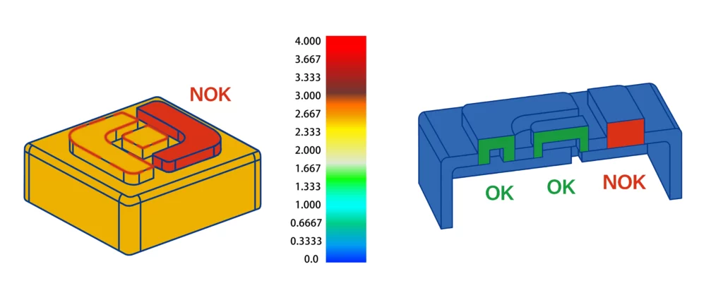
It is an important aspect of design, impacting the part’s strength, cost, and aesthetic appeal. It is our first primary consideration in design when we make a DFM. Ensuring a consistent thickness throughout your part helps prevent sink marks, warping, and other defects commonly associated with injection molding. We recommend a thickness ranging from 2 to 3 mm for the main body of your part.
Choose smooth transition when you need thickness variation
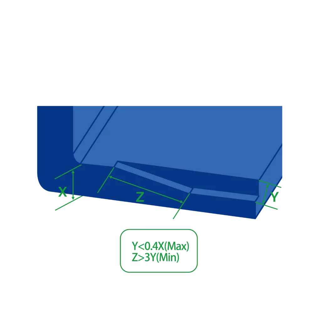
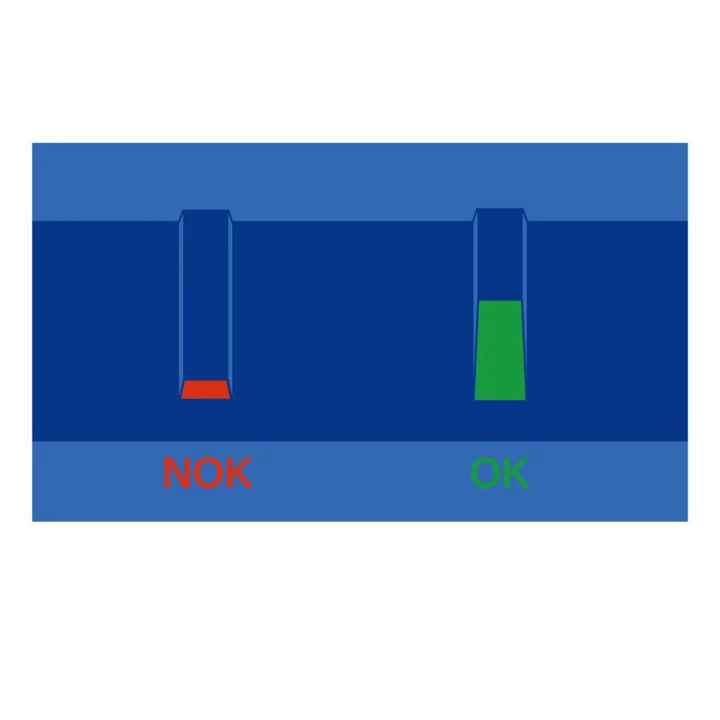
When wall thickness reductions are necessary, use chamfers or fillets to ensure a smooth transition between these sections. We recommend a radius that is 3 times the difference in wall thickness.
Similarly, the base of vertical elements such as ribs, bosses, and snap-fits should always have a radius at the base for optimal design and functionality.
Add ribs wisely to strengthen your parts
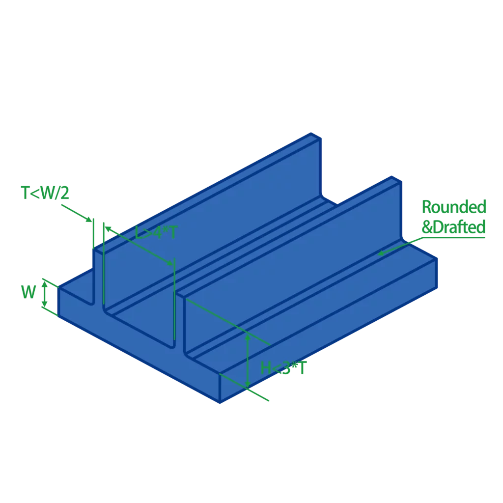
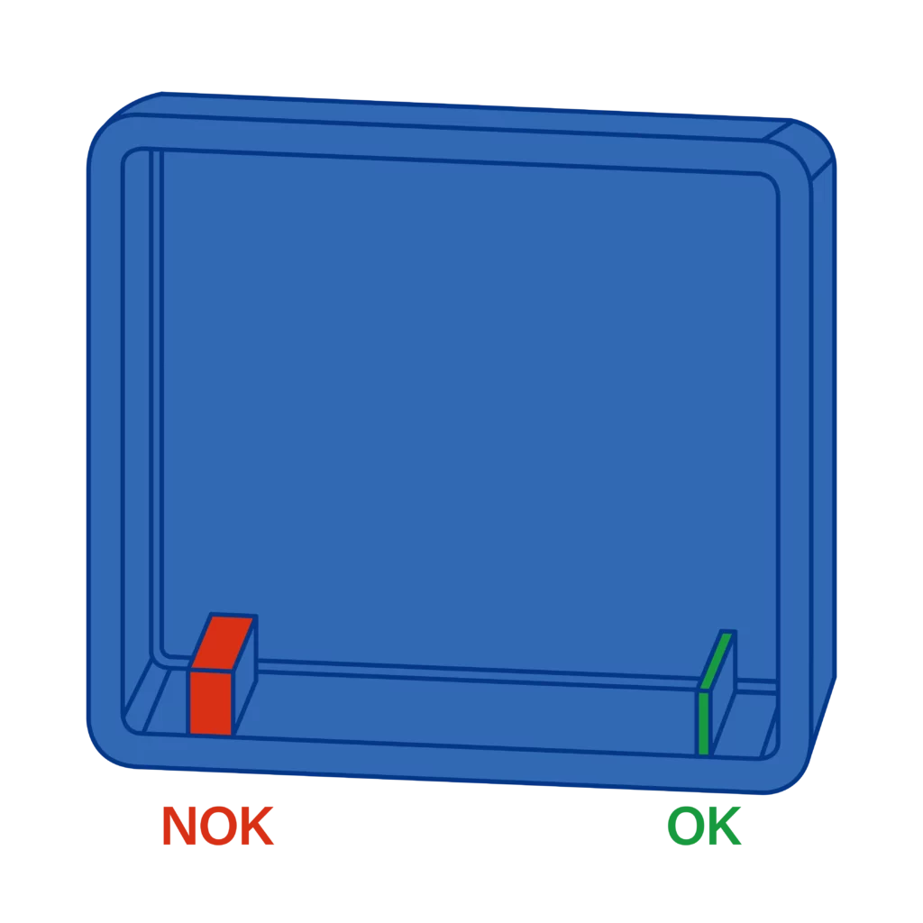
Ribs are vertical elements that enhance structural strength and increase the load-bearing capacity of a design. Here’s our advice for designing ribs effectively:
- Thickness: limit the thickness of the rib’s wall to no more than 50 to 60% of the main body’s thickness. This is particularly important to prevent shrink marks on visible surfaces.
- Fillets: incorporate a fillet at the base of each rib. Aim for a fillet radius that is about 0.25 to 0.5 times the part’s thickness.
- Height: keep the rib height as short as feasible, ideally not exceeding 2.5 times the thickness of the rib (2.5T). Opt for multiple shorter ribs rather than a few larger ones.
- Draft: apply a draft angle of 0.5° on each side of the rib to facilitate easier ejection from the mold and reduce stress concentrations.
Assembling by using some bosses
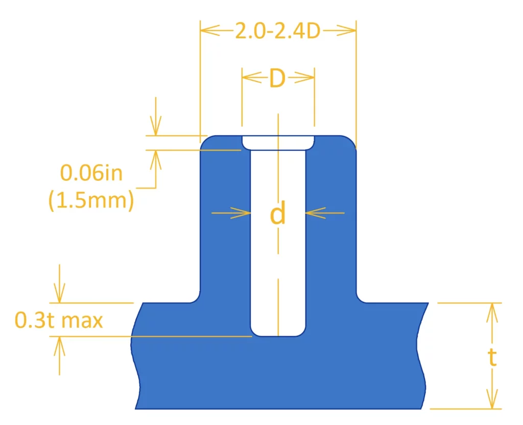
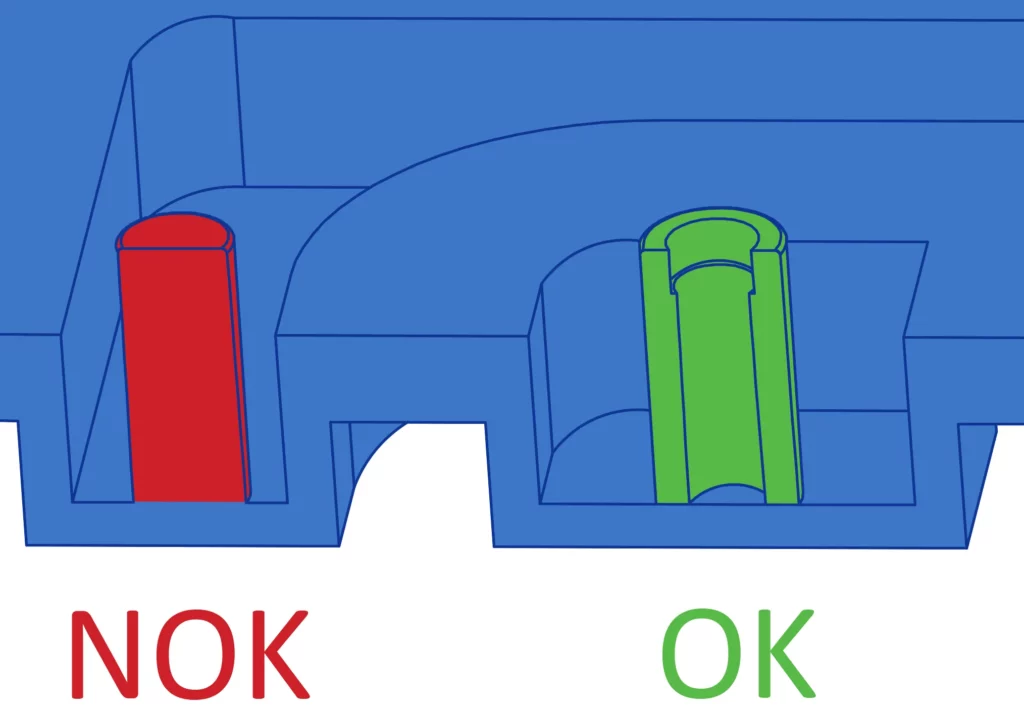
Bosses are vertical elements that serve as assembly points and enhance the structural integrity of a part, often used for fasteners like screws. Here’s our guidance for designing bosses:
- Inner Diameter: ensure the diameter is appropriate for its intended function. For self-tapping screws, refer to the manufacturer’s recommendations.
- Thickness: maintain the boss’s thickness at less than 50-60% of the main body’s thickness to reduce the risk of shrink marks.
- Draft: incorporate a draft angle into the boss design. In certain cases, you can reduce the draft angle to 0.1-0.2 degrees.
- Attachment: strengthen the bosses by designing additional ribs connected to them. This approach reinforces the bosses, providing additional support and stability.
Assembling by using snap-fits
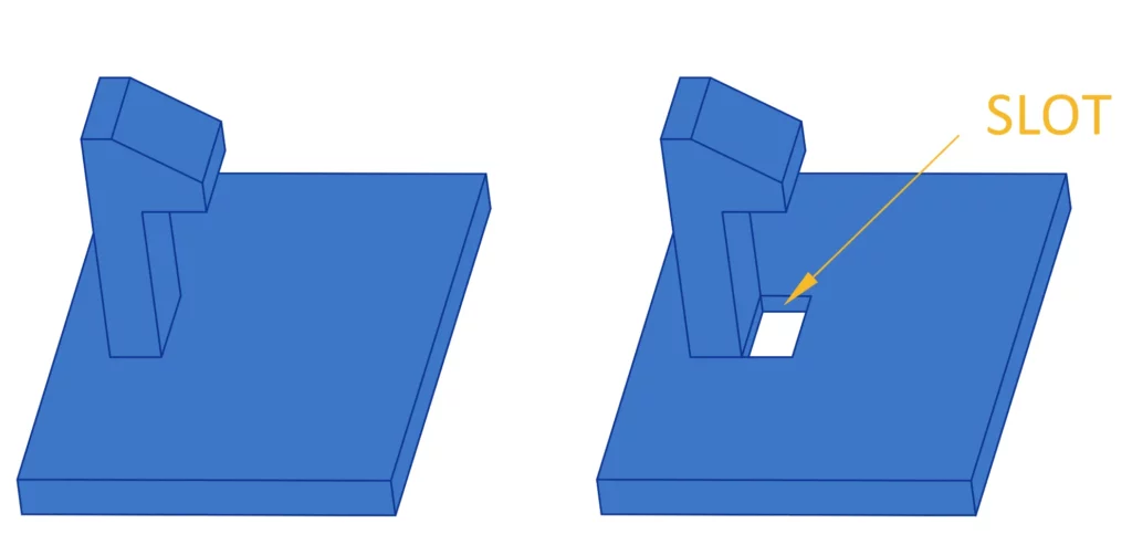
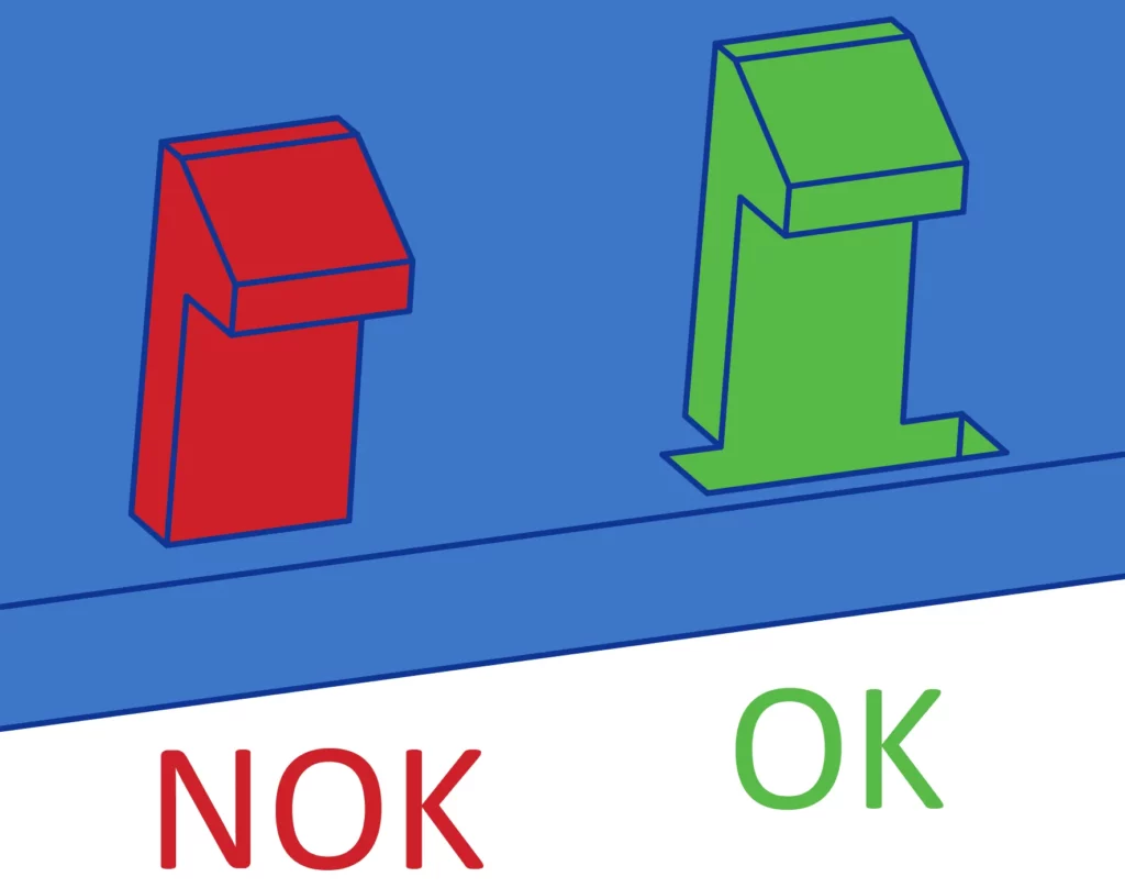
Snap-fits are an economical and quick way to join two parts without fasteners or tools. To eliminate excess movement in the mold, place a small opening at the base of the snap-fit. This is called a pass-through core. Here are our recommendations:
- Draft: add a 3-degree draft to the side walls of the snap-fit.
- Thickness: use a thickness of 0.5% of the main wall thickness.
- Width and length: adjust its shape to control the deflection and force.
Undercuts on the outside surface
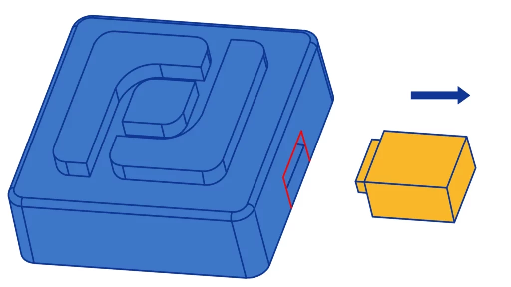
Undercuts in an injection-molded part are features that can impede its ejection from the mold. To facilitate smooth release, side-action movements are integrated as the mold opens. Our recommendations are as follows:
- Align undercut faces parallel to the parting line.
- Include a minimum draft angle of 0.5° in the direction of movement.
- This side-action movement may leave a visible line on the external surface (indicated by the red line in our picture). Our team will identify these lines during the Design for Manufacturing (DFM) review. In some instances, these lines can be reduced or removed through advanced mold movements, though additional costs may be incurred.
Find the interference and keep the right gaps
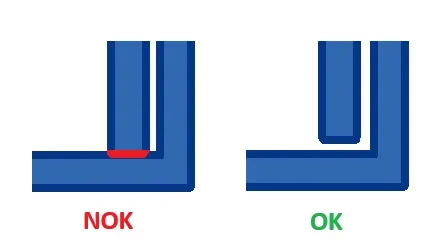
This may seem simple, but the first thing to check in an assembly is interference between parts. Conduct a thorough analysis; we’ll do the same on our end, and we often find errors that could have been avoided.
Injected parts generally have larger dimensional tolerances than those produced by CNC machining, for example. Therefore, it’s essential to consider the assembly of the plastic part with other components or with itself. We recommend allowing an assembly clearance of 0.1–0.2 mm (0.004–0.008 inches) to compensate for these variations. Keep in mind that it’s much easier to add plastic than to remove it once the mold is produced.
Add draft angle to your parts
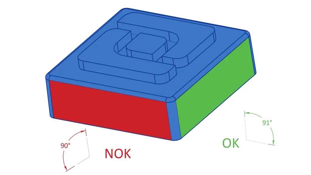
Draft angles are essential for part surfaces to ensure the smooth ejection of the part from the mold. Most CAD systems simplify the addition of draft angles, but it’s best to incorporate them in the final stages of part design to reduce complexity. Keep in mind that not all surfaces need the same degree of draft. Here’s our guidance:
- Mini draft is 0.5°
- Most common situations 2°
- All shutoff surfaces 3°
- Faces with textures 3° ( More detail on the section about draft angle above)
Add some radius on corners
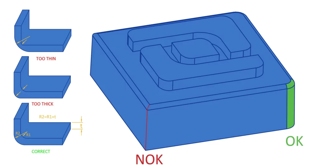
Sharp edges can lead to stress in the flow of raw materials and cause shrinkage marks. Additionally, they can increase production costs as their fabrication often necessitates the use of Electrical Discharge Machining (EDM). We advise you to design some rounded corners instead. We recommend that the internal radius be no less than half of the wall’s thickness, and the external radius should equal the sum of the internal radius and the wall thickness. It is important to ensure that both radii originate from the same point.
Last step: fix your tolerance
Ensure the correct assembly of your parts with their environment and define a dimensional control plan for the manufacturer using the appropriate tolerances. We advise following the normal class of the NFT58000 standard. Tighter tolerances are feasible in certain circumstances, but they significantly increase costs.
Cost optimisations for injection molding?
If you want to master the costs associated with injection molding, you must first understand the factors that influence this process. This section explores these factors and details practical ways to reduce the overall cost of injection-molded parts.
What affects the cost of injection molding?
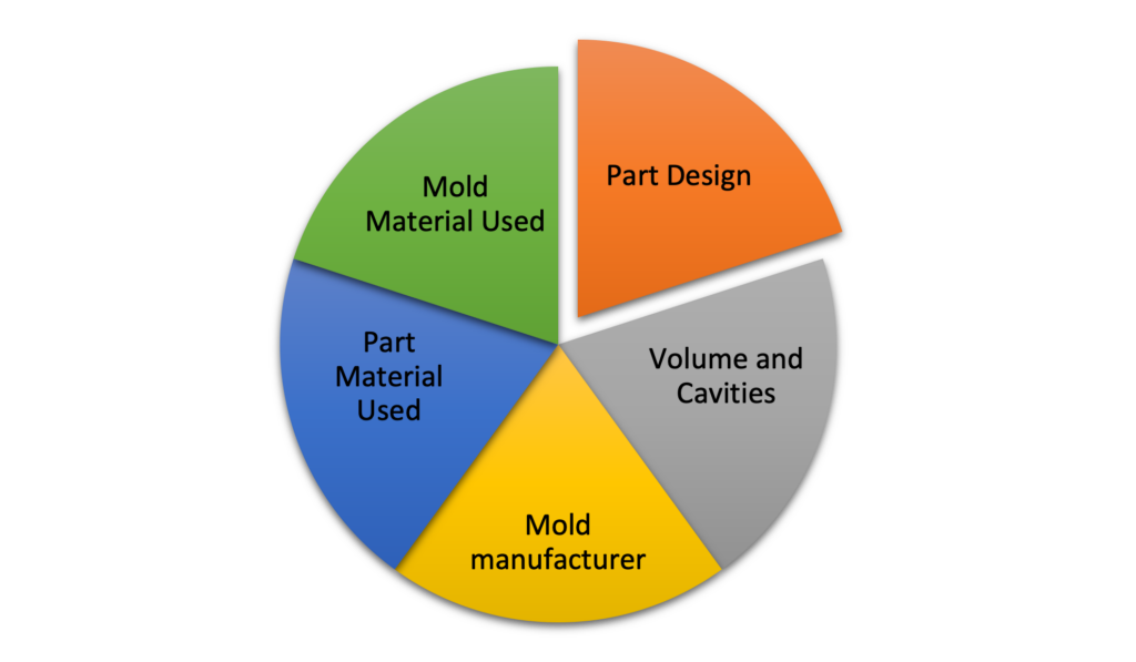
Several key factors influence the cost of plastic injection molding:
- Part design
Complex designs require intricate molds, increasing the cost. Complex parts might need additional machining like 5 axis CNC for undercuts, leading to longer production times.
- Part material used
The choice of resin significantly impacts the cost. Factors such as additives, molding temperatures, resin availability, and grade play a role. Some resins, like polypropylene and polyethylene, are more cost-effective, while others, like PA12 and PEAK, are more expensive due to their higher properties.
- Mold material used
Different steel hardness are used for mold creation. The choice of steel will depend on the thermoplastic produced, expected number of shots to produce and finish on the part. The choice of mold material also affects its maintenance needs and replacement frequency.
- Volume and cavities
One key factor in reducing production costs is increasing the number of cavities in the mold. A “multi-cavity mold” allows for multiple parts to be produced in each injection cycle, which significantly increases throughput and reduces the cost per unit. The more parts produced in each cycle, the lower the unit cost.
However, it’s essential to balance this cost-saving advantage with the upfront investment in the mold. A mold with more cavities is typically more complex and expensive to manufacture, often involving higher precision and additional engineering time. While **high-volume production** can justify the higher mold cost, this balance is crucial: for lower production volumes, the mold cost might outweigh the savings on unit prices.
- Mold manufacturer location
Molds, being complex tools, require significant time and labor to produce, making the location of the mold maker an important consideration. The so-called “low-cost” countries for injection tooling are Portugal and China.
To effectively manage costs, it is essential to take these factors into account during the planning phases.
How to reduce the price of injection molded parts
Reducing the cost of injection molded parts involves several strategic design and manufacturing considerations:
Simplifying part design by removing undercuts can reduce mold complexity and associated costs. Alternatives like sliding shutoffs, pass-through cores, or adjusting parting lines and draft angles can be more cost-effective.
Avoiding non-critical features such as textured surfaces or molded logos can lower costs. However, essential identifiers like part numbers should be included using cost-effective fonts and depths.
High-level cosmetic finishes often increase tooling costs. Opt for simpler finishes unless necessary for the product’s function or aesthetics.
Utilizing design for manufacturability analysis can identify potential issues or improvement opportunities, leading to more cost-effective designs and processes. We have strong expertise in plastics processing and will support you during this phase.
For high volume, multi-cavity molds can reduce piece-part price for higher volume production, although they might increase tooling costs. For low volume, family molds are effective for simultaneously producing a set of parts, provided they are made from the same material and are similar in size.
The size of the part influences mold size and complexity. Keeping parts within optimal size ranges ensures they fit comfortably within the mold without requiring excessive materials or larger molds.
Cost reduction in injection molding can be achieved through thoughtful design optimization, strategic material and mold selection, and efficient production planning. Each decision, from part design to mold configuration, plays a crucial role in balancing cost-efficiency with the quality and functionality of the final product. At Protolis, we have acquired extensive expertise in plastic injection for small-volume parts. Give us your specifications and we will be able to advise you effectively.
Conclusion
This comprehensive guide on injection molding delves into the essentials of this pivotal manufacturing process, exploring its history, operational mechanics, and various applications. Key aspects such as the injection unit, clamping unit, and mold design are crucial for the efficiency and quality of the production. The guide highlights the significance of material selection, design considerations, and process optimization for cost-effective and high-quality outcomes. Strategic approaches like eliminating undercuts, employing the core cavity approach, and leveraging design for manufacturability are discussed with an emphasis on reducing production costs and maximizing efficiency.
Protolis, with our expertise in injection molding, offers exceptional services in this domain. Our team provides comprehensive support, from design to production, ensuring high-quality and cost-effective solutions for diverse project needs. Contact us for expert guidance and efficient injection molding services. Our experts will get back to you within 24 hours.