In this guide, you will find comprehensive instructions for Compression Molding, a widely used method for crafting precise, high-quality rubber components.
As industries seek efficient and cost-effective manufacturing methods, compression molding for rubber stands out. This process delivers durable, high-quality flexible parts, combining design versatility with material compatibility. Gaining knowledge about this technique is essential for those looking to meet evolving market demands.
What is compression molding?
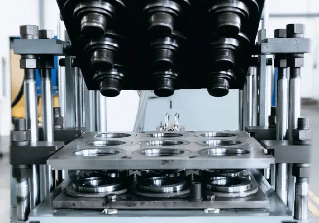
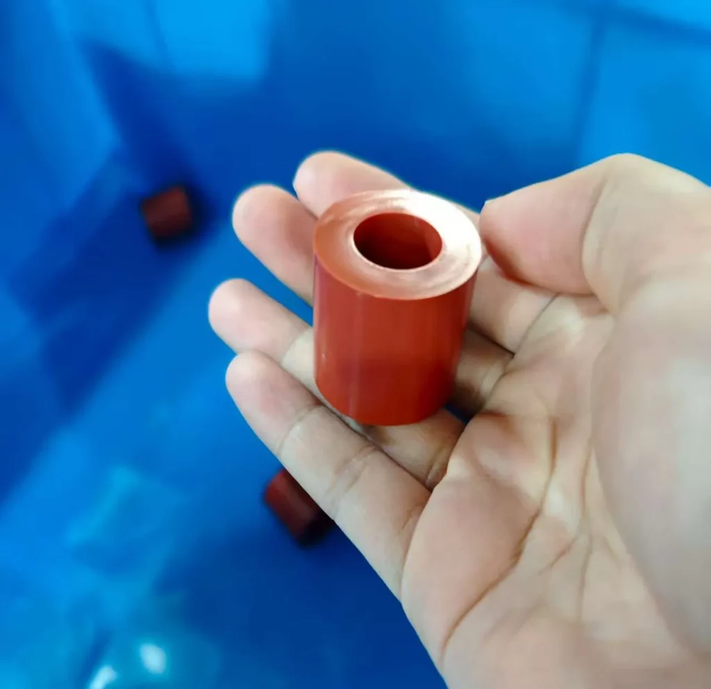
Compression molding is a manufacturing technique that involves placing pre-shaped material (called “preform”) like silicone or rubber into a heated mold cavity. The mold is then closed, shaping the material through applied pressure and heat. This process ensures the material fills the mold cavity and air voids are eliminated. The heat also serves to catalyze and harden the rubber, while pressure ensures thorough cavity filling and air removal. The thermotset materials then needs time to cure and harden properly, achieving the desired durability and shape consistency. This method is generally used to produce high-quality, precise low shore components across various industries.
How does compression molding work?
Rubber compression molding is a well-established method for creating durable flexible parts such as seals and gaskets. The process is straightforward, involving several key steps:
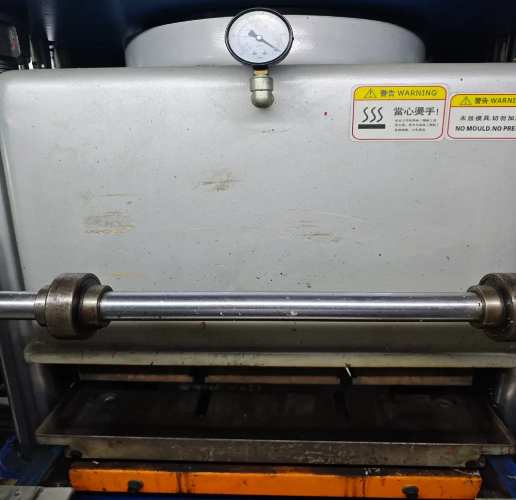
Machine preparation: The process starts with the compression molding machine, where the mold is preheated to optimize the curing of the rubber. The temperature settings and compression time are crucial as they affect the quality and characteristics of the final product.
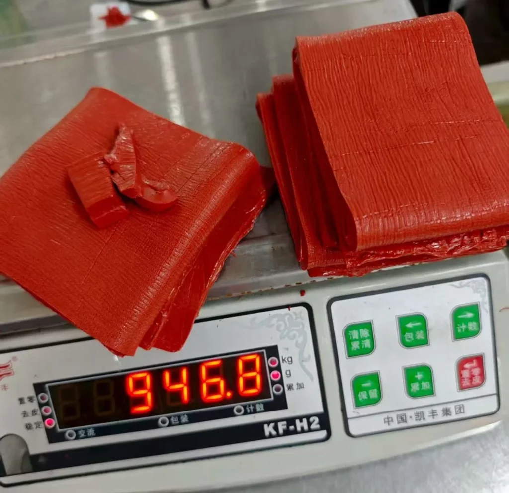
Material preparation: Rubber preforms are precisely weighed and checked before they are placed in the mold. This is important to prevent defects like weak parts due to underfilling or excess material (flash) due to overfilling.
Compression process: In this central phase, the preform is placed into the heated mold, which is then closed to compress the material. Heat and pressure are applied, causing the thermoset to conform to the mold’s shape. During this stage, any trapped air is also expelled in a degassing step to prevent voids or weak spots in the final product.
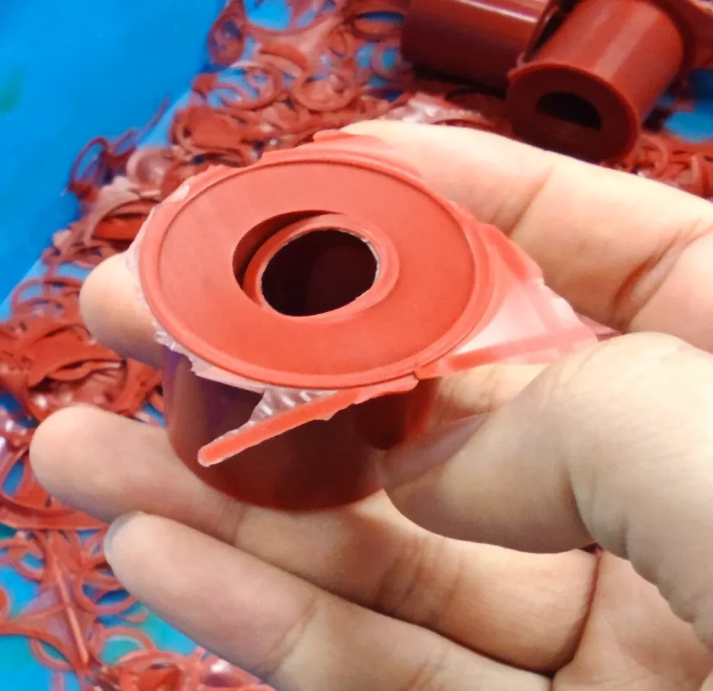
Deflashing: After the termoset material has cured, the mold is opened, and the excessive material is trimmed away. This step ensures that the final product meets precise dimensional requirements.
QC inspection and final product: The last step involves a thorough inspection of each part to ensure they meet the required specifications. Parts that pass the inspection are then packaged and prepared for dispatch.
This method is valued for its simplicity and cost-effectiveness. It is especially suitable for producing larger volumes of standard products. However, by adjusting the mold design and processing conditions, it can also be adapted for smaller batches or more customized specifications.
Key equipment for compression molding
Compression molding relies on several types of machinery to ensure the efficient production of rubber parts. Core equipment includes:
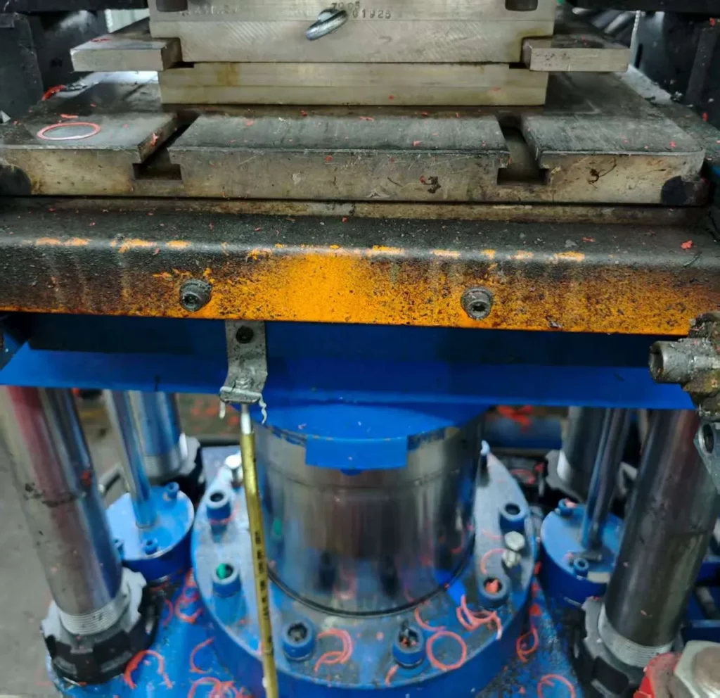
Large tonnage Press: These presses vary widely, with capacities ranging from 50 to 1,500 tons, accommodating different sizes and complexities of molded products.
Heating chamber: A dedicated chamber or oven heats the material to the required temperature for molding.
Mold: The mold comprises two halves—upper and lower—that are precision machined to form the desired product shape.
Automation systems: These include conveyor systems, hoppers, robotic arms, temperature control units, and mechanical ejection systems, all designed to streamline the molding process.
Air: Compressed air systems are employed for cleaning the mold cavities and part surfaces, ensuring they are free from debris.
Heating: Long, slender cylindrical electric resistors are used to maintain consistent heating.
Together, these tools play a vital role in the setup and operation of a compression molding facility, enhancing both productivity and product quality.
The history of rubber compression molding
Rubber compression molding is the oldest technique in rubber molding, tracing its origins to the 1890s. This method was pioneered by Harvey Firestone, who used it to manufacture the first consumer rubber products. Since its inception, the fundamental process has largely remained unchanged.
Rubber compression molding has continued to serve as a reliable method for producing various rubber items, owing to its simplicity and effectiveness. This historical method laid the foundation for the development of more complex rubber molding techniques used today.
What are the benefits of compression molding?
The compression molding of rubber and silicone offers several significant advantages that make it a preferred technique in many industries:
Low maintenance: The simplicity of the mold design makes it easy to clean and maintain. This reduces maintenance costs and downtime compared to more complex systems.
High strength and durability: The high pressure applied during molding compacts the material densely, yielding strong, durable parts. This ensures that products can withstand demanding applications.
Versatility in design: Custom molds allow for the creation of parts with diverse thicknesses and intricate features. This includes textures, ribs, bosses, inserts, and fastening points, enhancing the functionality of the final products.
No injection gate: The absence of a injection gate in the mold means there is no mark left on the final product. This enhances aesthetic quality and reduces finishing costs.
Flexibility with materials: This method is compatible with a broad range of rubber materials, facilitating versatility in production.
Multi-cavity production: Compression molding is well-suited for multi-cavity mold, allowing the molding of multiple parts simultaneously within a single cycle. Automation and advanced machinery help to minimize cycle times and boost output.
Cost-effectiveness: The straightforward tooling and design associated with compression molding generally involves lower initial costs. As production volume increases and if automation is possible, the overall cost per unit decreases, making it economically beneficial for large-scale production.
These benefits highlight why compression molding remains a cornerstone method in manufacturing, balancing cost, efficiency, and product quality.
What are the limitations of compression molding?
Rubber and silicone compression molding, while effective, does have its limitations:
Longer cycle times: Compared to faster molding techniques like injection and transfer molding, compression molding has relatively longer cycle times, up to 300 seconds. This is due to the extended periods needed for applying pressure, heating, and cooling the molds, which can slow down overall production efficiency.
Design constraints: This method supports the production of complex parts but struggles with intricate internal geometries or very thin walls. The dependence on preformed rubber and open molds restricts design flexibility, generally favoring simpler shapes.
Flash management challenges: A notable drawback of compression molding is the occurrence of flash—excess material that oozes out of the mold cavity. Managing flash can be labor-intensive, often requiring manual trimming or cryogenic deflashing. These additional steps introduce extra costs and can complicate the production process.
These limitations underscore the need for careful consideration when selecting compression molding for rubber parts, particularly where design complexity and production speed are critical factors.
Suitable materials for rubber compression molding
Compression molding effectively utilizes a variety of elastomers, each offering distinct properties and benefits for different applications. Here’s an overview of the most suitable materials for this process:
Natural rubber (NR): Derived primarily from latex, natural rubber exhibits a high stretch ratio and excellent resilience. It combines strength with waterproof qualities, making it highly versatile in various industries.
Ethylene propylene diene monomer (EPDM) rubber: EPDM stands out for its resistance to heat, light, and ozone, surpassing many natural and synthetic rubbers in these aspects. Commonly used in sealing applications, EPDM is integral in the automotive and construction sectors for weatherproofing and insulation.
Styrene-butadiene rubber (SBR): Known for superior abrasion resistance, SBR is widely used where durability is critical. Its resistance to water swell and compression set makes it ideal for high-impact industrial applications.
Nitrile rubber (NBR): NBR’s robust nature makes it suitable for components that require resistance to oils and chemicals. Its excellent compression and mechanical strength are valued in automotive and industrial sealing applications.
Silicone rubber: This rubber type offers exceptional temperature and abrasion resistance, alongside chemical stability and durability. Silicone rubber’s versatility makes it a preferred material in the medical, automotive, and culinary industries.
Butyl rubber (IIR): Butyl rubber is highly valued for its flexibility and gas impermeability, making it ideal for use where air and moisture exclusion is necessary.
Fluoroelastomer rubber: Distinguished by its excellent resistance to fluid and gas permeability, fluoroelastomer is essential for applications requiring high chemical and temperature resistance.
Each of these materials brings specific advantages to rubber compression molding, allowing manufacturers to choose the most appropriate elastomer based on the performance requirements and environmental conditions of the final product.
Technical properties
Product
Density(g/cm2)
Tensile Strength(MPa)
Hardness(Degree, Shore A)
Temperature Range(C)
Natural Rubber (NR)
1.15
17
50 (±5)
-20 to +70
Ethylene Propylene Diene Monomer (EPDM) Rubber
1.11 – 1.13
15.3
65 (±5)
-54 to +150
Styrene-Butadiene Rubber (SBR)
1.55
3.4 – 20
65 (±5)
-40 to +70
Nitrile Rubber (NBR)
1.2
15
65 (±5)
-25 to +90
Silicone Rubber
1.17 – 2.10
7 – 10
30 to 80 (±5)
-60 to +230
Butyl Rubber (IIR)
1.35
8
65 (±5)
-40 to +120
Fluoroelastomer Rubber
1.85
3.4 – 13.7
70 (±5)
-1 to +300
Table 1: Technical properties of various elastomers used in compression molding
How to choose the right elastomer for compression molding
When choosing an elastomer for compression molding, several key factors must be considered to ensure optimal performance and cost-effectiveness of the final product:
Material properties: Evaluate the tensile strength, hardness, service temperature range, and abrasion resistance of the rubber. These properties determine how well the material will perform under specific operational stresses and environmental conditions.
Application requirements: The intended use of the final product significantly influences material selection. Some elastomers excel in high-temperature environments, while others are better suited for high humidity or exposure to chemicals. Assessing the mechanical stresses and loading types that the product will encounter is crucial.
Cost efficiency: Budget constraints also play a critical role in material selection. Consider not only the cost of the material itself but also the associated processing and maintenance expenses. Opting for a more expensive elastomer might be justified by lower long-term costs due to enhanced durability and reduced maintenance needs.
Environmental compatibility: It is essential to choose materials that are compatible with the environmental conditions where the product will be used. This includes factors like UV exposure, ozone resistance, and potential contact with aggressive substances.
Taking these factors into account ensures that the selected elastomer meets all functional, economic, and environmental requirements for your rubber compression molding project.
What is the shore?
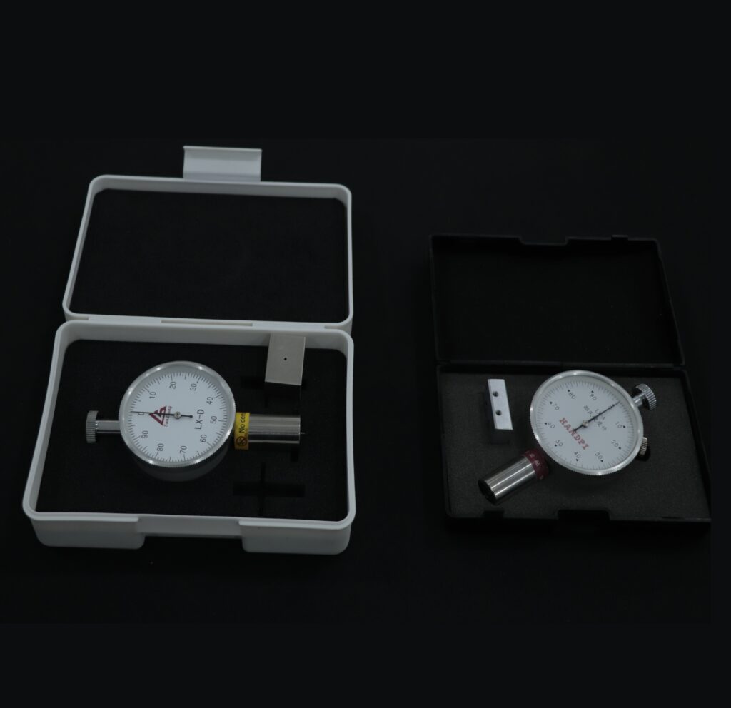
Shore hardness measures the hardness of elastomers, rubbers, and plastics. In compression molding, understanding Shore hardness is crucial, as rubber parts generally have lower hardness compared to typical plastic parts, which is one of the key reasons compression molding is used.
It is measured using a durometer, an instrument that presses a standardized indenter into the material’s surface. The Shore hardness value is determined based on how much the material resists indentation.
Shore hardness in compression molding affects:
Flexibility: higher Shore values indicate a stiffer, harder material, while lower values indicate a softer, more flexible material.
Durability and wear Resistance: harder materials often exhibit better wear resistance, making them suitable for applications involving high pressure or abrasive conditions.
Elasticity: softer materials with lower Shore values are more elastic and can return to their original shape after being deformed, which is critical for seals, gaskets, and other flexible parts.
There are different Shore scales for different types of materials. The most commonly used for compression-molded rubber and elastomers are the Shore A and Shore D scales.
Shore A is used for softer elastomers such as rubber and thermoplastic elastomers (TPEs). Materials tested on the Shore A scale are typically flexible and compressible. The scale values typically range from 0 to 100, with 0-30 indicating very soft rubber materials like gel-like elastomers, 30-60 for medium-soft materials such as seals, gaskets, and soft tire treads, 60-90 for harder elastomers used in industrial gaskets, belts, and automotive seals, and 90-100 representing very hard rubber, bordering on plastic-like stiffness.
Shore D values, typically ranging from 0 to 100, are used for harder materials like rigid plastics and very hard rubbers, with 0-30 representing flexible but firmer materials such as hard rubber rollers, 30-60 for semi-rigid plastics or hard rubber, 60-90 for hard plastics or rigid thermoset materials used in structural components, and 90-100 for very hard materials approaching glass-like hardness.
ASTM rubber standards
ASTM International, formerly known as the American Society for Testing and Materials, is a globally recognized organization that develops and publishes technical standards for a wide array of products, including rubber. These ASTM rubber standards are crucial for rubber manufacturers as they provide benchmarks for assessing the quality and safety of their products.
One key standard, ASTM D2000, enables buyers and manufacturers to describe rubber materials using a standardized language based on physical properties. This specification includes a system of numbers and letters that detail aspects such as the year of revision, units of measurement, material grade, durometer hardness, and tensile strength.
ASTM rubber standards facilitate effective communication between consumers and manufacturers, ensuring that product specifications are clear and universally understood. This helps in maintaining consistency and reliability across the rubber industry, enhancing product quality and consumer trust.
How to read ASTM rubber standards
Understanding ASTM rubber specifications is crucial for ensuring material compliance and performance. Take, for instance, the specification ASTM D 2000-3 M2BG714B14EA14EF11EF31 EO14 EO34 F17. Here’s how to decode this:
ASTM D 2000: This identifies the standard being applied.
-3: Indicates the last revision year, 2003.
M: Specifies that measurements are in metric units.
2: Represents the grade of the rubber.
B: Describes the type relating to temperature resistance.
G: Denotes the class linked to oil swelling resistance after a specified duration and temperature.
714: Details like durometer hardness and tensile strength are encoded here.
B14xxx: Suffix letters describe different properties of rubber, such as water resistance, heat resistance, tear resistance, adhesion, and more.
Each segment of the specification provides essential information about the rubber’s characteristics and expected performance under specific conditions.
Navigating the tolerances in rubber compression molding is essential for achieving the desired product quality. The Association for Rubber Products Manufacturers (ARPM) classifies these tolerances into four tiers, from high precision to basic levels, facilitating appropriate selection based on product requirements:
A1 – High Precision: This is the most stringent tolerance level, used for high-precision applications. It necessitates costly molds, fewer cavities per mold, and rigorous inspection and control measures.
A2 – Precision: Less stringent than A1, this level still ensures precision. It requires detailed inspection, though the methods are less complex than those needed for A1.
A3 – Commercial: This is a commonly used tolerance for commercial products where standard precision suffices for functionality and performance.
A4 – Basic: The least strict tier, A4, is used where some dimensional control is necessary but cost constraints are significant.
Tolerances are categorized further into fixed and closed dimensions.
Fixed dimensions are those that remain constant, machined into the top or bottom of the mold (without a parting line).
Closed dimensions are formed when the mold halves meet (with a parting line).
Tolerance tables in imperial (in) and metric (mm)
Nominal Dimension (in)
A1 Fixed
A1 Closure
A2 Fixed
A2 Closure
A3 Fixed
A3 Closure
A4 Fixed
A4 Closure
0 – 0.4
0.004
0.005
0.006
0.008
0.008
0.013
0.013
0.032
0.4 – 0.63
0.005
0.006
0.008
0.010
0.010
0.016
0.016
0.036
0.63 – 1
0.006
0.006
0.010
0.013
0.013
0.020
0.020
0.040
1 – 1.6
0.008
0.010
0.013
0.016
0.016
0.025
0.025
0.045
1.6 – 2.5
0.010
0.013
0.016
0.020
0.020
0.032
0.032
0.050
2.5 – 4
0.013
0.016
0.020
0.025
0.025
0.040
0.040
0.056
4 – 6.3
0.016
0.020
0.025
0.032
0.032
0.050
0.050
0.063
6.3 – over
x .004
x .005
x .005
x .008
x .008
x .010
Table 2: Rubber compression molding tolerance in inches
Nominal Dimension (mm)
A1 Fixed
A1 Closure
A2 Fixed
A2 Closure
A3 Fixed
A3 Closure
A4 Fixed
A4 Closure
0 – 10
0.1
0.13
0.16
0.2
0.2
0.32
0.32
0.8
10 – 16
0.13
0.16
0.2
0.25
0.25
0.4
0.4
0.9
16 – 25
0.16
0.2
0.2
0.32
0.32
0.5
0.5
1
25 – 40
0.2
0.25
0.32
0.4
0.4
0.63
0.63
1.12
40 – 63
0.25
0.32
0.4
0.5
0.5
0.8
0.8
1.25
63 – 100
0.32
0.4
0.5
0.63
0.63
1
1.1
1.4
100 – 160
0.4
0.5
0.63
0.8
0.8
1.25
1.25
1.6
160 – over
x .004
x .005
x .005
x .005
x .008
x .010
Table 3: Rubber compression molding tolerance in mm
Selecting the right tolerance tier is crucial for balancing product performance with manufacturing efficiency and cost. At Protolis, we are able to meet all these tolerance levels with extreme precision, ensuring high-quality products tailored to the specific needs of our clients.
What are the applications of rubber compression molding?
The compression molding process is versatile and suited for various industries due to its ability to produce robust, complex shapes. Here are five primary applications:
Automotive industry
Figure 2: Automotive rubber molded parts
Compression molding is extensively used to create durable automotive parts that withstand harsh conditions. Typical products include seals, gaskets, and hoses, which are essential for vehicle assembly and performance.
Medical devices
Figure 3: Medical rubber molded parts
The medical sector relies on compression molding to produce components that require high precision and hygiene. Examples include diaphragms, valves, and stoppers, which are critical for medical instruments and containers.
This process is ideal for manufacturing insulated parts used in electrical assemblies. Products like insulating boots, caps, and covers are made to prevent electrical hazards and ensure safety.
Consumer products
Figure 5: Rubber molded watch bands
Rubber compression molding is used to crafts various household items due to its flexibility in material and design. Common products include footwear soles, appliance handles, and durable watch bands, combining functionality with aesthetic appeal.
Construction and plumbing
Figure 6: Compression-molded O-rings
In construction, compression-molded rubber is used for vibration dampers and window seals, enhancing building integrity and energy efficiency. In plumbing, it produces washers and O-rings that prevent leaks and ensure long-term durability.
These applications showcase the adaptability of rubber compression molding in producing parts that meet strict industry standards and diverse functional requirements.
Possible finishes for compression molded rubber parts
The surface finish of compression molded rubber and silicone parts is crucial for their performance and longevity.
Factors influencing the surface finishing
Mold surface quality: The mold’s surface quality is crucial as it directly impacts the finish of the molded part. Different standards like SPI (Society of Plastics Industry) and VDI (Verein Deutscher Ingenieure) are used to specify the degree of polish.
SPI finishes range from A1 (high gloss) to D3 (rough textured), with varying degrees of smoothness achieved through different polishing methods like diamond buffing for high gloss and dry blasting for rough textures.
VDI finishes, on the other hand, use a numeric scale (e.g., VDI 12 to VDI 45), indicating the roughness from stone polishing to dry blasting.
Type of rubber: The rubber type affects the texture and quality of the surface finish. Different rubbers respond differently to the finishing process, with some achieving smoother finishes than others. For instance, natural rubber can achieve very smooth finishes, while synthetic rubbers might require specific conditions for optimal results.
Amount of mold release agent: The quantity and type of mold release agent used can affect the surface finish. Too much agent can lead to a duller finish, while too little might cause the rubber to stick to the mold, making it difficult to achieve a smooth finish. Silicone-based agents are generally preferred for their effectiveness and minimal impact on the finish.
Deflashing: The method used to remove excess material, or flash, from the molded part also affects the surface finish. Techniques like trimming or grinding need to be finely controlled to avoid surface damage, which can detract from the appearance and functionality of the part.
Each of these factors must be carefully managed to ensure that the molded rubber parts meet the required specifications for functionality and appearance. Selecting the right combination of mold quality, rubber type, release agent, and flash removal technique is crucial for achieving the desired outcome.
Surface finish classifications for compression molded rubber parts
The Association for Rubber Products Manufacturers (ARPM) classifies surface finishes into four categories:
F1: This is the highest quality finish, providing a smooth, polished surface without imperfections. It is achieved using highly polished steel molds. The tightest tolerances are applied for critical dimensions, and visual defects like parting lines, flow marks, and flash are almost entirely eliminated.
F2: It allows for very small, unpolished tool marks. It offers a polished finish but is less meticulous than F1. Some visible parting lines and slight flash might be present, but they do not affect the functionality of the part. Commonly used in automotive seals, gaskets, and industrial components where a clean appearance and reliable performance are important but not at the same stringent level as Class A.
F3: Known as a “commercial finish,” larger parting lines, flash, and minor surface imperfections are allowed, as long as they don’t compromise the performance or function of the part. Suitable for commercial applications where the primary concern is functionality rather than aesthetics, such as rubber mounts, bushings, and gaskets used in non-visible areas
F4: Lowest quality finish where cosmetic appearance is not a priority. Significant flash, parting lines, and surface irregularities are permissible as long as they don’t affect the part’s performance
Generally, F3 is sufficient for many applications unless a smoother surface is critical for the product’s function or appearance. Choosing a finer finish like F1 or F2 will increase mold costs due to the higher level of precision required in the mold’s surface.
Possible surface finishing methods
Here are several finishing methods for compression molded rubber parts, each tailored to enhance the properties and performance of the final product:
Fluorination: This process involves exposing the rubber part to a fluorine gas mixture in order to modify the surface properties. This modification makes the rubber more resistant to weather, temperature, and certain chemicals like solvents. The alteration is only surface-deep, preserving the core properties of the material.
Low friction coating: Various coatings are applied to reduce friction and enhance wear resistance. The coatings can be selectively applied to specific areas, enhancing flexibility in manufacturing.
Flocking: This technique uses man-made fibers, aligning them electrostatically on an adhesive layer. Flocked surfaces reduce friction, noise, and dirt accumulation, and improve moisture regulation, sealing, and electrical insulation. Flocking can be applied partially by masking non-target areas during the adhesive application.
Each of these methods is selected based on the specific requirements of the application. At Protolis, we offer various finishing options for our rubber compression molded parts. Our primary focus is improving our rubber components’ functionality, appearance, and performance.
Best design pratices for compression molding
Compression molding, like other manufacturing methods, has to strike a balance between quality and cost-effectiveness. This section outlines some essential practices to optimize designs for compression molding in a way that combines lower costs with high-quality results.
5 best practices for compression molded parts
Effective design for manufacturability (DFM) ensures that compression molded parts are not only easier to produce but also cost-effective and efficient in terms of production speed. Here are five best practices to consider when designing for compression molding:
Optimize wall thickness: Design parts with moderate wall thickness (1.3-25 mm or 0.051-0.98 inches) to balance material usage and cooling times. Thinner walls use less material and cool faster, reducing overall production costs.
Minimize undercuts: While compression molding can accommodate recessed features, designs should minimize undercuts. Undercuts may necessitate complex ejection mechanisms like sliders, increasing tooling expenses.
Smooth transitions: Avoid sharp corners and abrupt changes in wall thickness to ensure smooth material flow and uniform cooling. This helps in maintaining the structural integrity and aesthetic quality of the part.
Strategic parting line placement: Place parting lines thoughtfully to minimize their visibility, particularly in flash molds. Consider the impact of witness lines and flashes on the part’s appearance, even if it is not a cosmetic component.
Utilize suitable draft angles: Incorporate appropriate draft angles to facilitate easy part removal from the mold, reducing the risk of damage during ejection and improving the efficiency of the molding process.
At Protolis, we extend DFM guidance to our clients, ensuring their designs are optimized for compression molding. Our expertise helps in refining product designs to enhance manufacturability, driving down costs and speeding up time-to-market for all compression molded parts.
Cost optimisations for compression molding
Various factors influence the cost of compression molding projects. Understanding these factors is vital to managing expenses, so let’s take a closer look.
Compression molding vs. Injection molding
Compression molding and injection molding are two prominent techniques in the manufacturing of flexible parts. Here are five key differences between these methods:
Material placement: In compression molding, the raw material is placed directly into the open mold cavity and then compressed. In contrast, injection molding involves injecting molten material into a closed mold under high pressure.
Tooling complexity: Compression molds are typically simpler and less expensive to produce compared to injection molds, which require complex designs to accommodate the injection and cooling systems.
Cycle time: Compression molding generally has longer cycle times since each phase (heating, pressing, cooling) must be managed sequentially. Injection molding benefits from faster cycle times due to continuous, simultaneous processes.
Waste management: Compression molding can lead to more material waste in the form of flash (excess material that oozes out of the mold), which must be trimmed. Injection molding usually produces less waste, as the excess material can often be reused immediately.
Part consistency and detail: Injection molding allows for higher detail precision and more consistent part quality across productions due to controlled injection parameters and material flow. Compression molding may result in less uniformity in part consistency and detail, especially with more complex geometries.
Costing: Compression molding typically involves lower initial tooling costs, making it economical for low to medium-volume production. However, the per-part cost can be higher due to slower cycle times. In contrast, injection molding has higher initial tooling costs but benefits from lower per-part costs due to faster production rates and efficiency, suitable for high-volume production.
Feature
Compression Molding
Injection Molding
Material Placement
The raw material is placed directly into the open mold cavity.
The molten material is injected into a closed mold under pressure.
Tooling Complexity
Simpler and less expensive molds.
Requires complex molds with more detailed designs.
Cycle Time
Longer due to sequential process phases.
Shorter due to simultaneous processing steps.
Waste Management
More waste in the form of flash, which needs trimming.
Less waste and excess can often be reused.
Part Consistency & Detail
Less uniformity in part consistency and detail.
Higher precision and consistency in details.
Costing
Generally, initial tooling costs are lower, but the per-part cost is higher due to slower cycle times.
Higher initial tooling costs but lower per part cost due to efficiency and faster production rates.
Table 4: Comparison between compression and injection molding
Understanding these differences helps manufacturers select the most appropriate method based on their specific needs. Each technique offers unique advantages that are suitable for different applications in the plastics and rubber manufacturing industries.
Conclusion
Rubber compression molding stands as a foundational technique within the manufacturing sector, celebrated for its simplicity and effectiveness in producing durable low shore components across diverse industries. Despite its limitations, such as longer cycle times and design constraints, the technique’s advantages in low to medium-volume production are unmistakable, including cost-effectiveness, low maintenance, and the ability to handle various material types.
At Protolis, we offer premium rubber compression molding services tailored to meet the specific needs of our clients. If you are looking for high-quality, precision-molded rubber parts, contact us today to explore how our solutions can enhance your production capabilities.